Home
/ How To Draw Isometric View - Learn how to create them easily in short time.
How To Draw Isometric View - Learn how to create them easily in short time.
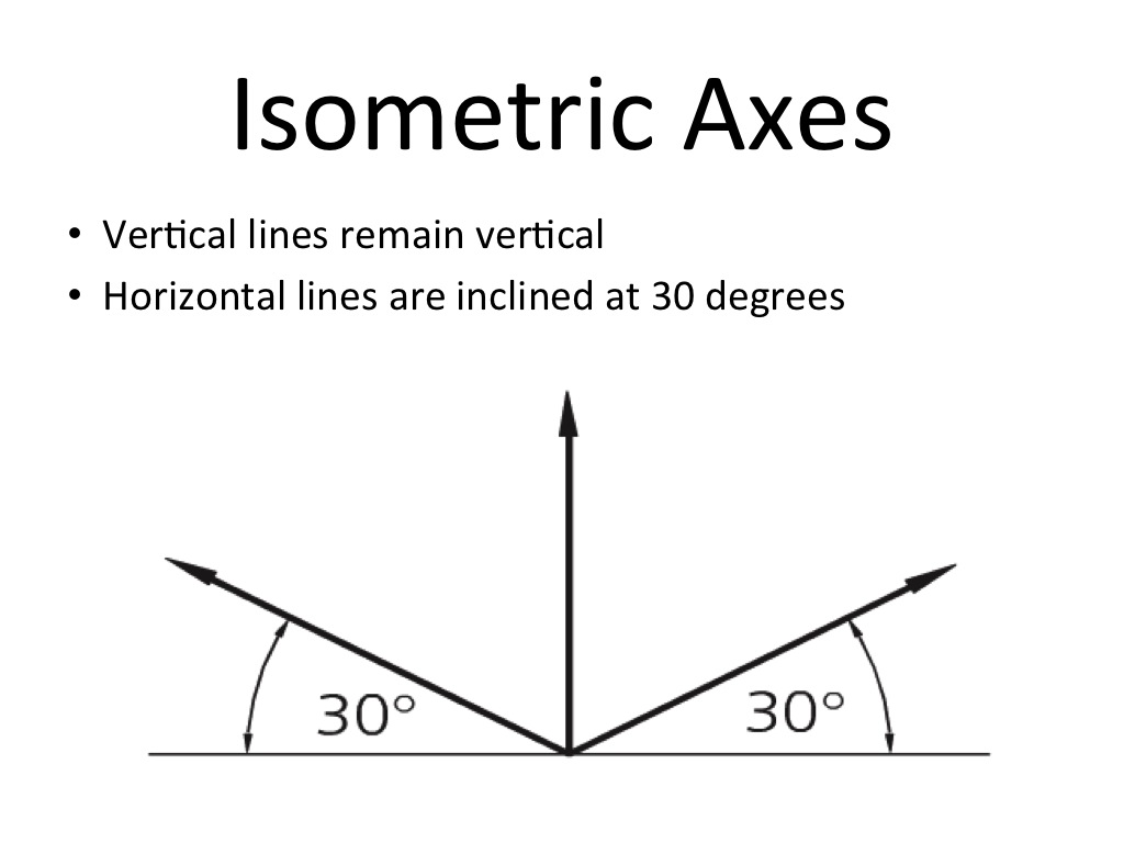
How To Draw Isometric View - Learn how to create them easily in short time.. All examples i've seen so far are of hexagons from a top down view, but i'm interested in the you can draw the hexagon in a regular square, then rotate the square into the diamond isometric shape, and finally squish it. Isometric drawings are not actual 3d drawings, they are made with 2d geometries but they the explanation given about how to make isometric drawing is very useful. Ask them to draw two different isometric views of the coded plan. First of all, we need to have an isometric grid. An angle of 30 degree is taken in all its sides in order to give a 3d look.
The geometric technique is a method preferred by. Today we will study isometric view of cylinder resting on it's base. Today we will study isometric view problem no.10. To avoid the confusion, the view drawn with the true scale is an isometric drawing or isometric view. Hi, its very simple,go to drafting setting,then snap and grid then change rectangular snap to isometric snap and close the window.
3D Drawing & Isometric Projection - Technical Graphics from sccs-tech.weebly.com To draw in an isometric view along the z axis you will need to define a new coordinate system orthogonal to the plane that you wish to draw in. Orthographic projection of cube of 40cm length, 40cm height and 40cm width is shown below. Learn how to create them easily in short time. To begin drawing a parallel projection, draw a vertical line for the z axis. Isometric drawing in autocad, tutorial with video. No matter how far the object is the scale will remain the same. Isometric drawings differ from other types of axonometric drawing, including dimetric and trimetric projections, in which different scales are used for different axes to give a distorted final image. How to draw an isometric object.
Activate by clicking on the ortho mode on the drafting settings are.
Isometric illustrations are often present in digital products because of their simplicity and functionality. Ask them to draw two different isometric views of the coded plan. I know there is probably a standardized template somewhere but i couldn't find it. It may be necessary to rotate a sample cube shape to help students to understand this challenge. Once each student has drawn two isometric views, have student pairs explain to each other how they produced their drawings. I've been asked a few times recently about how i draw isometric buildings. Isometric drawing in autocad, tutorial with video. Isometric drawings are most commonly used in technical drawings, patents, and manuals. In an isometric drawing, there is a specific set of angles between each axis. But before we do that, there's a little tweaking that we have to do in the top. Our pushy & pully game has some isometric view in place. This is in contrast to a perspective image drawing, which can have multiple vanishing points. An isometric view is a view in which the image has no vanishing point.
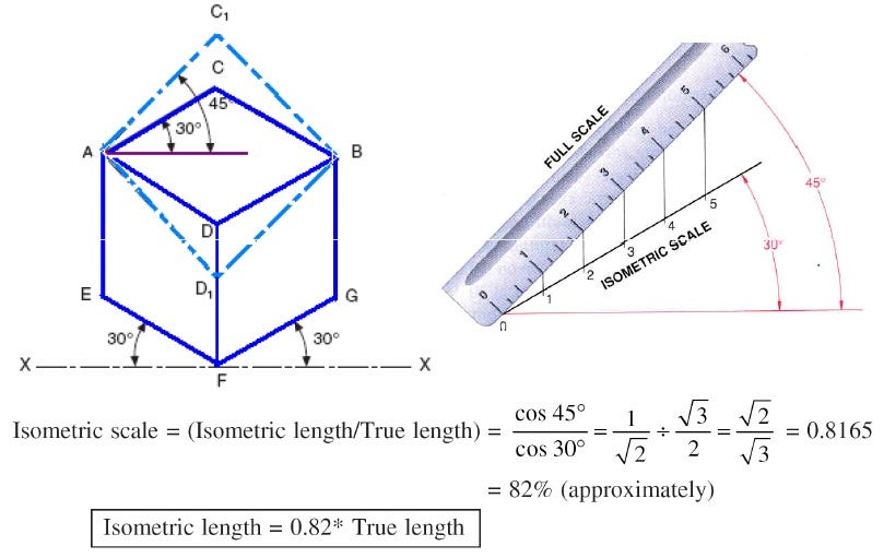
No matter how far the object is the scale will remain the same. I've only just started an engineering course and so far it's involved a lot of drawing which i usually can do but i can't seem to figure out how to 'place' this object to make an isometric view. Ask them to draw two different isometric views of the coded plan. With the help of this scale, the actual dimensions are transformed into isometric dimensions. There are a lot of resources and tutorials on how to do this, i'll explain you my method.
Designer's Guide to isometric Projection | by Alexander ... from miro.medium.com Spin the shape around by 45. I'm having trouble drawing an isometric view of this shape: Once each student has drawn two isometric views, have student pairs explain to each other how they produced their drawings. Isometric illustrations are often present in digital products because of their simplicity and functionality. First of all, we need to have an isometric grid. There are a lot of resources and tutorials on how to do this, i'll explain you my method. Isometric drawings are most commonly used in technical drawings, patents, and manuals. If you have any douts, please comment us.
Spin the shape around by 45.
No matter how far the object is the scale will remain the same. Today we will study isometric view of cylinder resting on it's base. Today we will study isometric view problem no.10. Drawing isometric projection actually means representing the proper accurate drawing with some. An angle of 30 degree is taken in all its sides in order to give a 3d look. I've been asked a few times recently about how i draw isometric buildings. You can draw impressive and complex isometric designs effortlessly once you learn the trick. Learn how to create them easily in short time. How to draw isometric scale useful for isometric projection in engineering drawing. As you can see as you can see the view is something in between top down and with a certain angle. It is frequently in use in many professions like game design solution: Isometric drawings differ from other types of axonometric drawing, including dimetric and trimetric projections, in which different scales are used for different axes to give a distorted final image. Ask them to draw two different isometric views of the coded plan.
First of all, we need to have an isometric grid. I've only just started an engineering course and so far it's involved a lot of drawing which i usually can do but i can't seem to figure out how to 'place' this object to make an isometric view. 1) draw two basic 30 degree guidelines, one to the left and one to the right, plus a vertical guideline in the centre of the drawing. To avoid the confusion, the view drawn with the true scale is an isometric drawing or isometric view. Drawing isometric projection actually means representing the proper accurate drawing with some.
bnykllr: Object A & B (Isometric) from 3.bp.blogspot.com Please like our video and share to your friends. In an isometric drawing, there is a specific set of angles between each axis. Activate by clicking on the ortho mode on the drafting settings are. Orthographic projection of cube of 40cm length, 40cm height and 40cm width is shown below. It may be necessary to rotate a sample cube shape to help students to understand this challenge. An angle of 30 degree is taken in all its sides in order to give a 3d look. How to draw isometric scale useful for isometric projection in engineering drawing. Than change the viewpoint in for example se.
I'm having trouble drawing an isometric view of this shape:
Spin the shape around by 45. Learn how to create them easily in short time. 1) draw two basic 30 degree guidelines, one to the left and one to the right, plus a vertical guideline in the centre of the drawing. Use some rectangles to get an interesting floor plan. Drawing items we take out of the video on the 3d modeling in autocad part 1. I've been asked a few times recently about how i draw isometric buildings. Activate by clicking on the ortho mode on the drafting settings are. In figma or sketch app, draw three shapes using the rectangle tool. Our pushy & pully game has some isometric view in place. Isometric drawings are not actual 3d drawings, they are made with 2d geometries but they the explanation given about how to make isometric drawing is very useful. In an isometric drawing, there is a specific set of angles between each axis. As you can see as you can see the view is something in between top down and with a certain angle. An angle of 30 degree is taken in all its sides in order to give a 3d look.
